Disclaimer
This documentation reflects the M-Bus specification from the late 1990s. It is for information only and should not be used for product design or any other application or engineering.
Publication of the current M-Bus specificationMore and detailed informations about the specifications of the physical layer are listed in the document ‘WG4N85R2.DOC’ § .
4.1 Principles of Operation
The M-Bus is a hierarchical system, with communication controlled by a master (Central Allocation Logic). The M-Bus consists of the master, a number of slaves (end-equipment meters) and a two-wire connecting cable: see Figure 8. The slaves are connected in parallel to the transmission medium - the connecting cable.
 Fig. 8 Block diagram showing principle of the M-Bus System
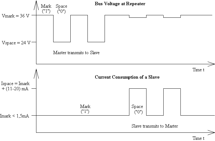
In order to realize an extensive bus network with low cost for the transmission medium, a two-wire cable was used together with serial data transfer. In order to allow remote powering of the slaves, the bits on the bus are represented as follows:
The transfer of bits from master to slave is accomplished by means of voltage level shifts. A logical “1” (Mark) corresponds to a nominal voltage of +36 V at the output of the bus driver (repeater), which is a part of the master; when a logical “0” (Space) is sent, the repeater reduces the bus voltage by 12 V to a nominal +24 V at its output.
Bits sent in the direction from slave to master are coded by modulating the current consumption of the slave. A logical “1” is represented by a constant (versus voltage, temperature and time) current of up to 1.5 mA, and a logical “0” (Space) by an increased current drain requirement by the slave of additional 11-20 mA. The mark state current can be used to power the interface and possibly the meter or sensor itself.
 Fig. 9 Representation of bits on the M-Bus
The transmission of a space by a slave results in a slight reduction in the bus voltage at the repeater due to output impedance, as can be seen in Figure 9.
The quiescent state on the bus is a logical “1” (Mark), i.e. the bus voltage is 36 V at the repeater, and the slaves require a maximum constant quiescent current of 1.5 mA each.
When no slave is sending a space, a constant current will be drained from the repeater which is driving the bus. As a result of this, and also the resistance of the cable, the actual Mark voltage at the slaves will be less than +36 V, depending on the distance between the slave and the repeater and on the total quiescent current of the slaves. The slave must therefore not detect absolute voltage levels, but instead for a space detect a voltage reduction of 12 V. The repeater must adjust itself to the quiescent current level (Mark), and interpret an increase of the bus current of 11-20 mA as representing a space. This can be realized with acceptable complexity only when the mark state is defined as 36 V. This means that at any instant, transmission is possible in only one direction - either from master to slave, or slave to master (Half Duplex).
As a result of transmission in the master-slave direction with a voltage change of 12 V, and in the answering direction with at least 11 mA, besides remote powering of slaves a high degree of insensitivity to external interference has been achieved.
4.2 Specifications for Bus Installations
Segmentation
An M-Bus system can consist of several so-called zones, each having its own group address, and interconnected via zone controllers and higher level networks. Each zone consists of segments, which in turn are connected by remote repeaters. Normally however, an M-Bus system consists of only a single segment, which is connected via a local repeater to a Personal Computer (PC) acting as master. Such local repeaters convert the M-Bus signals into signals for the RS232 interface. From now on, the local repeater will simply be termed the “repeater”, and the combination of PC and local repeater termed the “master”.
Cable
A two-wire standard telephone cable (JYStY N20.8 mm) is used as the transmission medium for the M-Bus. The maximum distance between a slave and the repeater is 350 m; this length corresponds to a cable resistance of up to 29 W . This distance applies for the standard configuration having Baud rates between 300 and 9600 Baud, and a maximum of 250 slaves. The maximum distance can be increased by limiting the Baud rate and using fewer slaves, but the bus voltage in the Space state must at no point in a segment fall below 12 V, because of the remote powering of the slaves. In the standard configuration the total cable length should not exceed 1000 m, in order to meet the requirement of a maximum cable capacitance of 180 nF.
Plug
There is so far no standard or recommendation for a M-Bus plug to connect the meters to the bus system, but the Usergroup investigates in defining a proper connector. Three different plugs have to be defined for the connector at a) the installation mode b) meter to fixed installation and c) meter to handheld connection.
4.3 Specifications of the Repeaters
See chapter ‘Electrical Requirements Master’ in the document ‘WG4N85R2.DOC’ § .
4.4 Slave Design
The requirements for slaves are listed in the paper ‘WG4N85R2.DOC’ § . The following characteristics are part of it:
-
Transmission Characteristics
The slaves are designed to be constant current sinks with two different currents, whereby the current which is “sunk” must not vary by more than 0.2 % for 1 V voltage change on the bus. In order to transmit a Mark, a so-called Unit Load consisting of a constant current of 1.5 mA maximum is specified. If the slave needs more current, an appropriate number of additional Unit Loads must be used. When sending a Space, the slave increases its current consumption by 11-20 mA. In order to receive data, the slave detects the maximum value Vmax of the bus voltage, which can be between 21 V and 42 V. With a bus voltage of more than Vmax - 5.5 V, a Mark should be registered, and with a voltage of less than Vmax - 8,2 V, a Space should be registered.
-
Remote Powering
The bus interface - that is, the interface between the slave and the bus system - must take the current it needs from the bus system. If possible, the complete slave should be fed from the bus; in this case, should the bus fail, it must automatically switch over to battery operation, or the significant data must be saved. If the slaves are operated only from batteries, it is necessary that a battery life of several years should be attained, in order to reduce maintenance costs.
-
Protective Measures
The bus interfaces of the slaves are polarity independent: that is, the two bus lines can be interchanged without affecting the operation of the slaves. Besides protection aspects, this also results in simplified installation of the bus system. In order to maintain correct operation of the bus in case of a short circuit of one of the slaves as mentioned before these must have a protection resistor with a nominal value of (430± 10)W in their bus lines. This limits the current in the case of a short circuit to a maximum of 100 mA (42 V / 420 W ), and reduces the energy converted into heat in the bus interface.
M-Bus Transceiver TSS721
In order to meet the requirements for the slaves mentioned above, an IC was developed by Texas Instruments Deutschland GmbH, namely the Transceiver (i.e. Transmitter and Receiver) TSS721. The use of the TSS721 in M-Bus slaves as the interface to the bus reduces the number of components needed, and therefore the cost of slaves. Apart from the transmission and reception of data in accordance with the M-Bus specification, this IC also provides translation from and to the operating voltage of the microprocessor to which it is connected, in order to be able to communicate with it. The communication can take place at baudrates from 300 to 9600 Baud. Additional features include integrated protection against reversed polarity, a constant 3.3V power supply for the microprocessor, and the prompt indication of failure of the bus voltage.
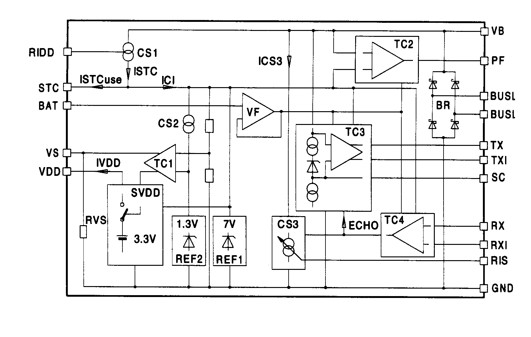
By referring to Figure 10, the individual functions of the TSS721 will now be explained in more detail:
 Fig. 10 Block Diagram of the Transceiver TSS721 [4]
-
Reversed Polarity Protection
The bus lines are first taken to the bridge rectifier BR via the external protection resistors Rv (in this case, of 215W in each line), in order to provide reversed polarity protection. This rectified voltage can be accessed at the VB (Voltage Bus) pin. In order the avoid a reduction of the voltage as a result of rectification, when reversed polarity protection can be dispensed with, the bus voltage may also be connected directly between the VB and GND pins.
-
Reception
The comparator circuit TC3 is provided to detect signals from the master; it adjusts itself to the Mark voltage level with the help of the capacitor SC. This capacitor is charged up to 8.6 V under the Mark voltage when in the Mark state, and discharged during the Space state. The ratio of charge to discharge current is more than 30 to make any kind of UART protocol work indepedently of the data contents. The voltage across the capacitor SC results in dynamic matching of the comparator to the Mark level. From the relationship between the charging and discharging current results the requirement in the transmission protocol that at least every eleventh bit (with adequate certainty) must be a logical 1 - that is, a Mark. This guarantees that SC is not discharged too much, and that matching to the Mark voltage level is always effective. With a voltage of 7.9 V under the Mark level, the TSS721 gives a logical 0 to the TX pin (0 V) and to the inverted TXI pin (Supply Voltage).
-
Transmission
The signal from the microprocessor applied to the RX Pin or RXI Pin (inverted) is converted into a current by TC4 and the constant current source CS3. When there is a Mark at the inputs (RX or RXI), the quiescent current is taken from the bus with the help of the constant current source. If however the processor transmits a Space, then TC4 switches on the constant current source CS3, and consequently the additional pulse current. The quiescent current can be adjusted over a certain range with the resistor Ridd, and the pulse current adjusted with Ris. In order to allow the processor to recognize collisions, the signal on the RX(I) pins is echoed on the TX(I) pins.
-
Powering of the Processor
The TSS721 provides a nominal voltage of 3.3 V at its VDD Pin, in order to supply power to a microprocessor. When limited to a standard load, according to the data sheet this processor may however consume an average current of about 600 m A. For pulse current requirements, use is made of the reservoir capacitor STC. When connection is made to the bus, this capacitor will be charged at up to 7 V, and the power supply at the VDD pin is activated at VSTC = 6 V. The TSS721 signals the failure of the bus voltage at the PF-Pin (power fail), so that the processor has time to store its data in e.g. an EEPROM, whilst powered by the reservoir capacitor. In addition, the transceiver permits the connection of a battery to the VDD Pin should the bus fail, by means of FET at the VS Pin (voltage switch). In such a case, and when the microprocessor is powered solely with a battery, the voltage must also be taken to the BAT Pin in order to match into the TSS721.
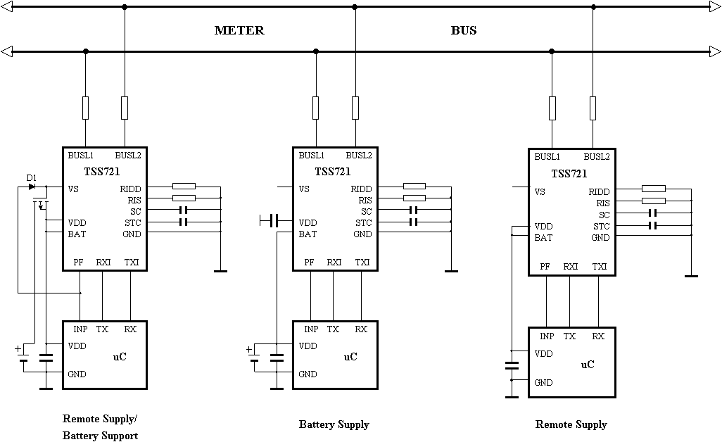
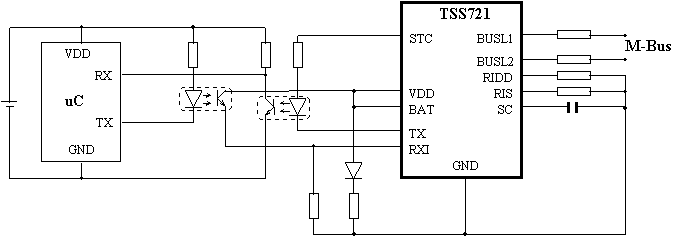
Figure 11a) shows three alternative operating modes for the TSS721 which can be used to power a microprocessor. It shows that the processor can be supplied exclusively by the transceiver (remote supply), normally from the TSS721 and with bus failure from a battery (remote supply/battery support), or only by the battery. Few external components are needed to build a complete slave with the TSS721, apart from the microprocessor or microcontroller and the components specifically required for the sensing elements. Besides Fig. 11b) shows a basic optocoupler application.
 Fig. 11a) Operating Modes of the TSS721 for Powering a Microcontroller [4]
 Fig. 11b) Basic optocoupler application [4]