Disclaimer
This documentation reflects the M-Bus specification from the late 1990s. It is for information only and should not be used for product design or any other application or engineering.
Publication of the current M-Bus specification2.1 Applications and Definitions
The methods by which data processing systems communicate with each other are classified according to the distances involved. With world-wide networks the term used is Global Area Networks (GAN), whereas networks covering continents or large land masses are known as Wide Area Networks (WAN); Local Area Networks (LAN) are concerned with distances up to a few kilometers, and are limited to specific geographical areas, such as laboratories, office buildings and company premises. Such local networks are used, for example, to link terminals, computers, measuring equipment and process automation modules with one another.
In the majority of local networks, one or other of the following methods (topologies) are used to link the components in a system:
-
Star Topology
Each component is linked to a central processor unit with an individual transmission line. The equipment can transmit to the central unit either sequentially or simultaneously. One disadvantage of this arrangement is the increased requirement for cabling.
-
Ring Topology
In this case, the components are connected to one another in a ring, and the data are transferred from point to point. This topology has the disadvantage that, should a single equipment fail, the complete network will be out of action.
-
Bus Topology
The components are connected together with a common transmission line, with the result that at one instant only one equipment can transmit data. This topology is very cost-effective, it will not be disturbed if one of the components fails, and it allows the transmission of data to all components (Broadcasting) or to specific groups in the system (Multicasting).
 Fig. 1 Network Topologies
A serial bus can be defined as a transmission path over which the participants transmit their data serially (i.e. bit after bit), sequentially in time and using a common medium. In contrast, in parallel bus systems the individual bits which form a character are transmitted simultaneously by a certain number of data lines. This results in increased costs for cable and connectors; the transmission time is shorter than with a serial bus.
2.2 Basic Functions of Bus Systems
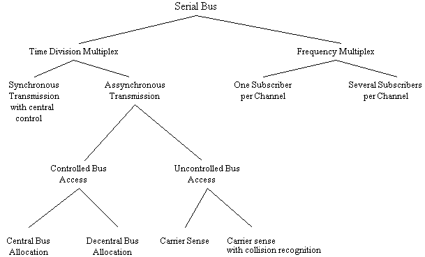
The following diagram is intended to provide an overall view of the various forms of serial bus systems:
 Fig. 2 Classification of Serial Bus Systems According to Transmission and Access Techniques [1]
The first subdivision can be made according to the multiplex technique which is used. With frequency multiplex, the frequency spectrum of the transmission medium is divided into frequency bands, each representing a channel. Each participant is then allocated a channel. In the next section, the kind of synchronization and access techniques which are used will be described in order to classify serial bus systems using time division multiplex.
2.2.1 Access Techniques
Since in bus systems the transmission medium is used by all participants together, account must be taken of their various transmission requirements. The methods used by participants who want to transmit over the bus are known as access techniques. These techniques must ensure that several stations do not transmit simultaneously, and so cause bus conflicts or collisions, and that each participant can transmit for at least a certain minimum time. The sharing of the bus among stations who want to transmit is implemented with an allocation logic system.
With central allocation logic, the central bus controller receives a request to use the bus and then takes the decision as to whether, and if so when, the user can occupy the bus. For this purpose various methods are used to register the bus occupation request:
- direct registration by means of an individual branch line to each equipment
- periodical interrogation (polling) of the participants as to their transmission needs
- requests sent on a common line with identification of the sender
- allocation of the bus according to a predetermined time frame without taking account of individual requirements
The advantage of central allocation logic is the reduced complexity which is required at individual stations.
With decentralized allocation logic, each participant is provided with functions which allow him to recognize whether the bus is already in use. There are various methods which can be used to determine whether the bus is occupied:
- mutual interrogation of stations by means of a request line for each station
- periodical bus allocation, by passing “ownership” of the bus from station to station
- CSMA (Carrier Sense Multiple Access): The participants have the ability to check whether the bus is transmitting data, and to transmit their own data if it is found to be free. To avoid collisions, which could arise as a result of signal transit times, with certain bus systems (e.g. Ethernet) the stations are able to use their own data on the bus to determine whether there is a bus conflict. In such a case, the transmission will be interrupted and repeated after an appropriate time interval.
A higher degree of logic complexity at each station is needed to implement decentralized allocation logic, but this system also has the advantage that a fault in the central bus controller will not result in a complete breakdown of the bus.
2.2.2 Synchronization of Participants
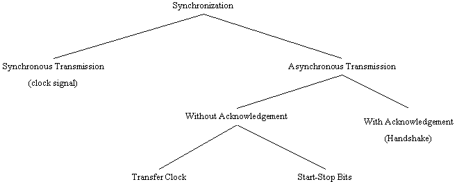
Synchronization is to be understood as the coordination in time of the communicating participants, with regard to signal transmission and reception. The various methods of synchronization can be classified into data transmission which is synchronous and that which is asynchronous (see Figure 3).
With synchronous transmission, a stable clock signal is supplied either by the central station or one of the communicating partners, which serves to measure transmission times. With asynchronous transmission, a distinction must be made between techniques with and without signal acknowledgment. Where there is signal acknowledgment (handshake), the sender shows with a specific signal on the line that he has data to send, and waits for an acknowledgment from the receiver. Techniques without acknowledgment use a transfer clock on a special line for parallel bit transmission, or start and stop bits to frame a character for bit-serial transmission.
 Fig. 3 Classification of Synchronization Techniques
2.2.3 Error Processing
The reasons for transmission errors in bus systems are widely known. These include in particular electromagnetic interference from outside, for example: inductive coupling at mains frequencies; high-frequency interference as a result of sparking at the brushes of motors or arcs of discharge lamps; capacitive coupling to other lines; or directly coupled currents from ground loops as a result of multiple grounds.
A bus system must ensure that transmission errors are recognized and corrected. For this reason additional information is supplied with the data to be transmitted, which allows the data to be checked on reception.
Particularly with asynchronous transmission, an additional parity bit is often transmitted with each character. This parity bit is constructed so that the parity conditions (an even number of ones, or an odd number of ones) are fulfilled. Another method is the creation of a block check character from specific mathematical operations e.g. addition without carry (Check Sum), which is derived from all the data. The receiving station can detect whether there have been transmission errors by comparing the check character it has received with one which it has calculated itself. The parity bit allows only the recognition of an odd number of faulty bits.
In order to correct errors the recipient sends an acknowledgment, which indicates that the transmission has been either error free, or that there have been transmission errors. For the same purpose the transmitter checks that the receiver acknowledges the reception of data in a certain period of time. If the time limit is exceeded (Timeout), or if a transmission error has been reported, then the sender repeats the transmission a predetermined number of times.
The Hamming Distance is used in order to specify the security of a character code; this is the number of errors (minus one) which can be recognized for all cases.
2.3 The OSI Reference Model
The ISO-OSI reference model provides a basis for the development of standards for Open Systems Interconnection (OSI). This model devised by the “International Organization for Standardization” (ISO) is intended to ensure that information from systems made by various manufacturers, and having different architecture, can be exchanged and interpreted in accordance with standardized procedures.
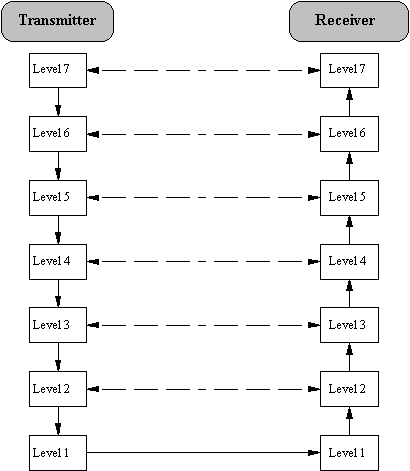
This model arranges the communications functions in seven layers, each of which has a virtual connection to the appropriate layer of the communicating partner. Only on the lowest layer (Layer 1) is there a physical connection for exchanging signals. Each layer, with the exception of Layer 1, obtains the necessary service from the layer below it. The OSI model merely defines the servicing and functions of the layers, but not the technical realization (the protocols) within the layers.
Two user programs can exchange information on Layer 7, if there is agreement between them (i.e. there are protocols) on the following points [2]:
- the representation of information in Layer 6
- the flow of communications (contents and form) in Layer 5
- the completeness of the information and the security of transport in Layer 4
- the way information should be transferred through the network in Layer 3
- the security of transmission in Layer 2
- the physical medium in Layer 1
| 7 | Application Layer | |
| 6 | Presentation Layer | Application Oriented Layers |
| 5 | Session Layer | |
| 4 | Transport Layer | |
| 3 | Network Layer | Transport Oriented Layers |
| 2 | Data Link Layer | |
| 1 | Physical Layer |
Fig. 4 The Seven Layers of the OSI Model
The functions of the individual layers shown in Figure 4 will now be explained in more detail:
-
Physical Layer
The basic physical connection between the communicating partners takes place in this lowest layer. The mechanical and electrical coupling to the transmission medium is determined here, by specifying (among other things) the cable, the distances involved, the pinning of connectors, and the way the bits are represented.
-
Data Link Layer
This layer is responsible for assuring that a reliably operating connection is made between two participants. For this purpose the protocol of this layer determines the methods for protecting transmissions, the telegram structure, methods of accessing the transmission medium and for the synchronization and addressing of participants. By making use of the procedures described in Section 2.2.3 it should be possible to identify and correct faults in the Data Link Layer.
-
Network Layer
The network layer undertakes the choice and implementation of the best transmission route in a network between the communicating parties, and provides this service (Routing) to the Transport Layer. This function is of particular significance when different networks need to be connected by means of Gateways.
-
Transport Layer
The transport layer represents the boundary between the application oriented layers 5 to 7, and the transport oriented layers 1 to 4. Its job includes guiding the information through the network, controlling the flow of information and the grouping into individual packets.
-
Session Layer
The session layer provides procedures for the opening, the orderly progressing, and the termination of a communication “session”. In this is included also the control of the dialogue between systems: that is, the determination of their respective transmission prerogatives.
-
Presentation Layer
The data of the application are converted in the presentation layer into a data format which the receiving application can interpret. This layer thus implements the matching of data formats and the conversion of codes.
-
Application Layer
This top layer represents the interface between the open system and the user. It offers the user or his program a service allowing him to work easily with the system. Application programs which need to be developed can thus access the functions of the open system via the protocol of the application layer.
In the following diagram the route to be followed by data from the transmitting to the receiving application can be seen, indicated by the continuous arrows. At the transmitting side information (Overhead) which is necessary for transmission and processing is added to the actual data in each layer; at the receiving side this information is removed again in the reverse order after processing.
 Fig. 5 Data Transmission in Accordance with the OSI Model